

Track monitoring to RIL for safe rail infrastructure
During construction work next to and beneath tracks, we monitor track position, settlement and deformation to the standard of RIL 883.8100A01. With automatic data capture, remote transmission and proactive alerting.
- Position nominal
- Height nominal
- Cant nominal
- Twist nominal
Why track monitoring
Why track monitoring is essential during construction work
Construction work near the track, temporary conditions and interventions in the subsoil can cause settlement, displacement and twist. Compliant geo-monitoring provides evidence and enables a fast response.
Request a quoteConstruction near the track
Continuous recording of track geometry during construction states directly next to or beneath the track.
Drilling and piling works
Interventions in the subsoil cause settlement. The smallest changes in position are detected early.
Temporary bridges
Monitoring of position, cant and twist on temporary structures in the track area.
Switches and crossings
Geo-monitoring for tracks and switches to RIL requirements, even at sensitive junctions.
Traceability
Unbroken time series document the track condition before, during and after the construction phase.
Automatic alerting
If thresholds are reached, the system alerts immediately, around the clock and without an on-site check.
RIL 883.8100A01
These are the parameters required by the guideline
RIL 883.8100A01, Deutsche Bahn’s guideline for track monitoring, defines minimum requirements for measurement and evaluation in geo-monitoring of tracks and switches. At least four parameters are monitored, and the scope can be extended as part of the risk assessment.
- 01
Position
Lateral position of the track, captured via measuring points on the sleeper grid.
- 02
Height
Vertical position of the rail, to reliably detect settlement and heave.
- 03
Relative height (cant)
Height difference between the two rails, decisive for running safety.
- 04
Twist
Change in cant over a defined length, a key safety criterion.
Measuring point density
Every 5 sleepers per rail, typically 3.00 m at a 60 cm spacing.
Measuring range
At least 25 m beyond the area of possible change.
Extendable
Gauge and absolute track geometry depending on the risk assessment.
Simulation
Detect settlement before it becomes critical
Subsoil interventions cause the track to sag. See how the height position is measured continuously and what happens once the defined threshold is reached.
Demonstration only
Readings, measuring point M4
Continuous capture, 15 min cycle
- Position 0.0 ok
- Height (settlement) 0.0 ok
- Cant 0.0 ok
- Twist 0.0 ok
Threshold reached, alarm triggered
Notification sent to site management and operator
Measurement technology
Total-station monitoring as the standard
For track monitoring to RIL requirements, high-precision total-station monitoring is the standard approach. Precise, automated and with continuous remote transmission.
Capture
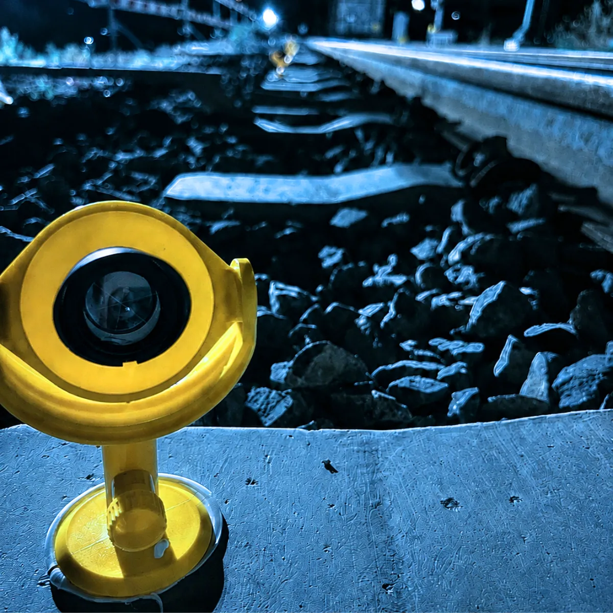
Prism targets on the sleeper grid
Reflector targets are placed on the specified grid and automatically sighted by the motorised total station.
Evaluation
Automated measurement cycles
Defined measurement intervals deliver a robust evaluation of track geometry without manual intervention on site.
Operation
Remote transmission and alerting
All readings are transmitted securely and continuously checked against the defined thresholds. If a threshold is exceeded, alerting is triggered automatically.
Automated total station monitoring
Automated total station monitoring of track: how the system works
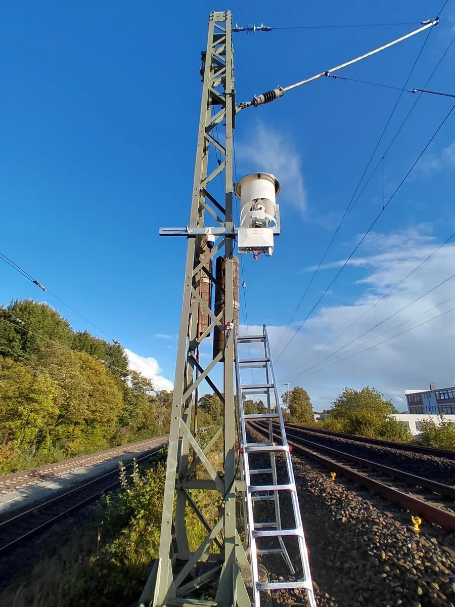
A robotic total station measures the track from a fixed position, usually on an overhead line mast next to the track. It sights 360° prisms on the sleepers fully automatically, determines its own position in every cycle from reference prisms outside the zone of influence and derives position, height, cant and twist of both rails from the coordinates. The data reach the platform without anyone on site, where they are checked against the warning and alarm values of RIL 883.8100A01.
- σ ≤ ±3 mm
- Accuracy for position, height and cant required by RIL 883.8100A01 up to 160 km/h
- 0.5″
- Angle measurement accuracy of the total station (manufacturer specification)
- 0.6 mm + 1 ppm
- Distance measurement accuracy to the prism (manufacturer specification)
- ≥ 4
- Reference prisms per total station outside the zone of influence
- ≤ 1 h
- Measuring cycle per total station, readings at least hourly
Accuracy
Millimetre accuracy, verified
RIL 883.8100A01 requires a standard deviation of ±3 mm for position, height and cant at line speeds up to 160 km/h. We work with robotic precision total stations with an angle measurement accuracy of 0.5″ and a distance accuracy of 0.6 mm + 1 ppm to the prism. Redundant observations, repeat and check measurements document the achieved measurement uncertainty.
Reference prisms
Stable reference outside the zone of influence
At least four reference prisms per total station sit outside the influence of excavations, jacking and open-cut work, before and behind the monitored track section, on overhead line masts or on neighbouring buildings. The mast carrying the instrument is not a reference point: the station position is recalculated from the reference prisms in every cycle.
Monitoring prisms
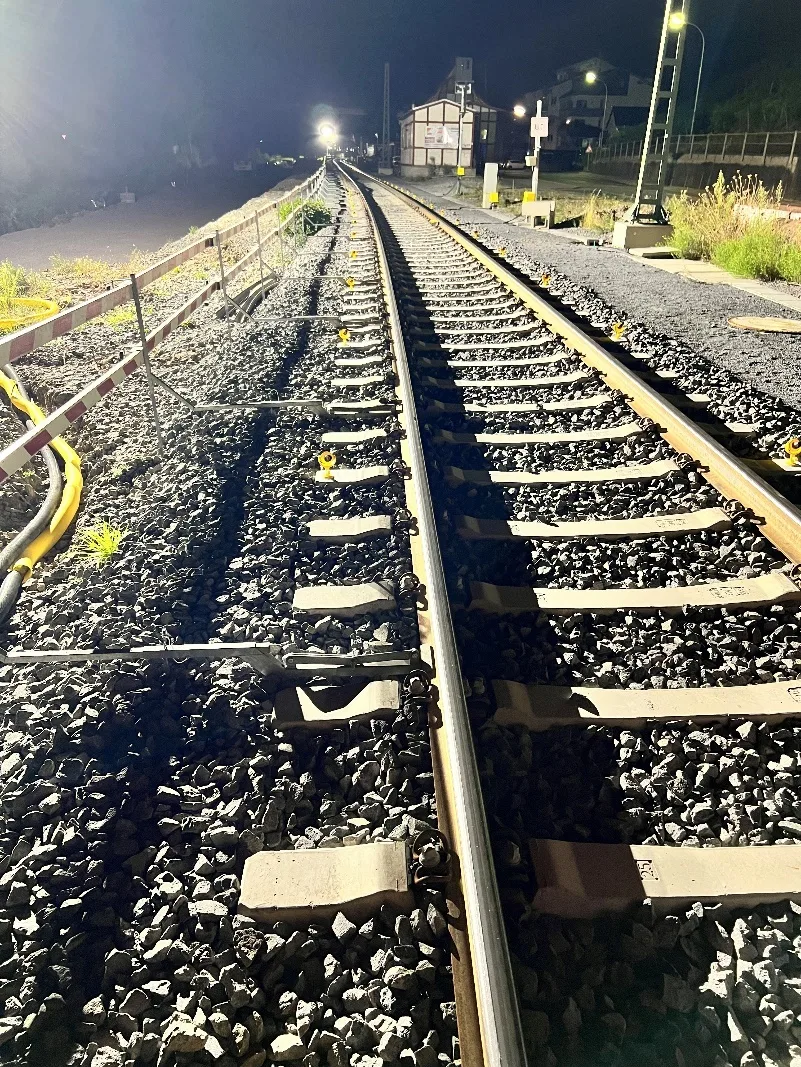
360° prisms every five sleepers
The monitoring prisms sit on the outside of the sleeper ends, every five sleepers on each rail, around every 3 m. Because both rails are measured, cant and twist follow directly from the readings. Installation takes place at night during a track possession. Spare prisms are kept in stock; a damaged prism is replaced in the next possession and taught in again.
Temperature compensation
Temperature and air pressure measured at the station
Air temperature and air pressure change how the measuring beam travels, and the mast itself moves in the daily temperature cycle. Temperature and air pressure sensors at the station therefore measure continuously. These values are used to apply an atmospheric correction to every distance measurement, and the station position determination from the reference prisms also captures any movement of the mast. What remains is the movement of the track.
Data transfer and power
Mobile network, mains or self-sufficient
After each cycle, the station sends the readings securely over the mobile network to the evaluation server, where they are stored and available in real time on the online portal. Power comes from a fixed connection where one is available; otherwise the station runs self-sufficiently on solar modules and buffer batteries.
Evaluation
Position, height, cant, twist
Every cycle is compared with the baseline measurement, which runs over several cycles before construction starts. The platform calculates position, height, relative height (cant) and twist and checks them against the warning and alarm values. Automated routines check every time series for completeness and plausibility and flag jumps and outliers.
Alerts
Warning value and alarm value
Following RIL, there are two levels: the warning value and the alarm value as the threshold for immediate intervention. Alerts go by email, and by SMS on request, to the group of people named in the alarm plan of the client. If a station fails, the system reports that too, so that no gap in monitoring goes unnoticed.
Remote operation
Operated and maintained remotely
Operating status, communication and power supply of each total station are monitored continuously. Measuring programmes and intervals can be adjusted remotely. On site, we service the stations every six months and as required. Reports: baseline report, weekly regular reports and a final report, with monitoring continuing for at least two weeks after the works end.
Warning and alarm values by line speed
Values as specified in RIL 883.8100A01, tables 1 to 3, as used in our measuring programmes. DB can adjust them after the baseline measurement.
| Line speed | Position and height | Relative height (cant) | Twist |
|---|---|---|---|
| 80 km/h | 12 / 21 mm | 10 / 15 mm | 3.5 / 6.0 ‰ |
| ≤ 120 km/h | 10 / 17 mm | 8 / 13 mm | 3.5 / 6.0 ‰ |
| ≤ 160 km/h | 8 / 14 mm | 7 / 11 mm | 3.5 / 6.0 ‰ |
Warning value / alarm value
Everything from a single source
One point of contact for the entire track monitoring project
You don\u2019t get separate parts, you get a complete solution. From the monitoring concept to ongoing operation, everything is handled in one place.
- 01
Concept
Defining parameters, thresholds and the measuring-point grid according to RIL and the risk assessment.
Learn more - 02
Installation
Prism targets and the total station are installed correctly and commissioned with a documented baseline measurement.
Learn more - 03
Maintenance and operation
Continuous measurement cycles, well-maintained sensors and robust evaluation throughout the entire critical phase.
Learn more - 04
Monitoring and alerting
Round-the-clock remote transmission, automatic alerting on thresholds, on request as an outsourced department.
Learn more
Infrasolute platform
All readings on the Infrasolute platform
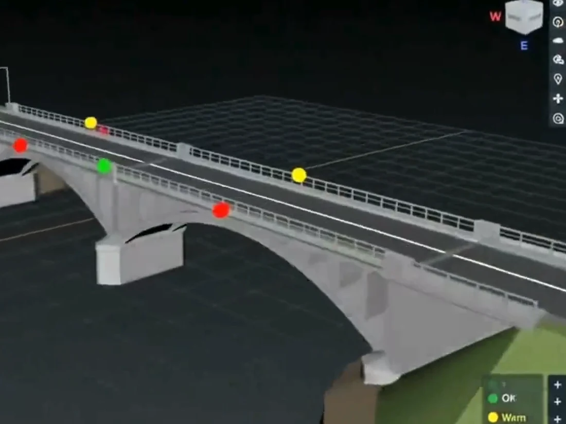
The sensors transmit their readings to the platform. There they are continuously checked against your limit values, evaluated with AI and documented, accessible in the browser around the clock.
Platform modules
A monitoring concept for your construction project at the track
Tell us about your project in the track area. We will propose an RIL-compliant monitoring concept and get back to you shortly with a no-obligation quote.
 Roman Koch

Applications
Where track monitoring shows its strength
Wherever construction work can affect track geometry, continuous geo-monitoring provides safety and traceability.
- Construction near the track
- Bridges with individual support points
- Subsoil interventions
- Drilling and piling works
- Temporary bridges
- Switches and crossings
Monitoring for rail operators, train operating companies and engineering offices
Whether a construction firm, an operator or a planning office: we combine track monitoring and RIL expertise for everyone involved in the rail environment.
Frequently asked questions about track monitoring
Which parameters must be monitored as a minimum?
At what spacing are measuring points placed?
How large does the measuring range need to be?
Why is total-station monitoring the standard?
How accurate is automated total station monitoring of track?
What are the reference prisms for?
How is the influence of temperature compensated?
How is the total station powered, and how do the data reach the portal?
When is additional gauge monitoring required?
Does Infrasolute also take care of ongoing operation?
Project inquiry
A monitoring concept for your construction project at the track
Tell us about your project in the track area. We will propose an RIL-compliant monitoring concept and get back to you shortly with a no-obligation quote.
[email protected]